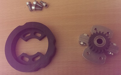
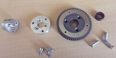
Les engrenages : j’ai choisi des engrenages de module 1, le choix est assez restreint, acier ou nylon renforcé, la géométrie est la même, épaisseur 15, moyeu épaisseur 10 ; au regard des couples transmissibles, le nylon renforcé suffit très largement, et c’est tout de même plus facile à usiner : en effet, il va falloir amincir les moyeux, amincir l’engrenage lui même, aléser …
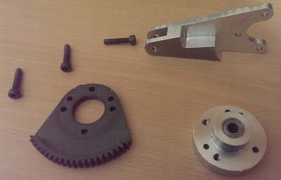
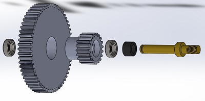
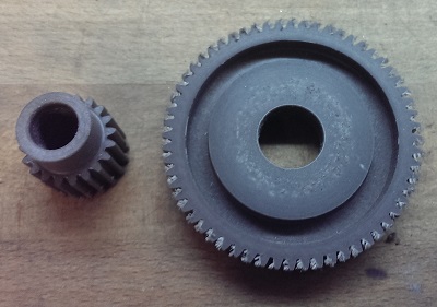
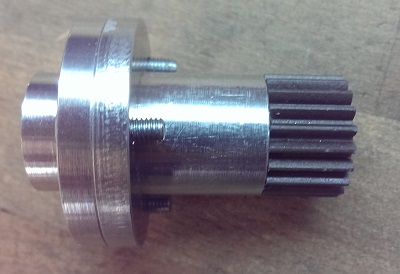
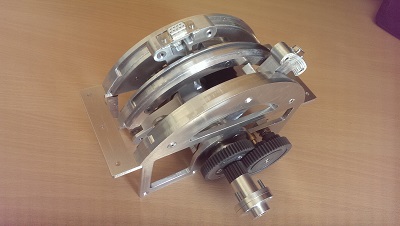
Pour exemple, le pignon double de l’axe secondaire : je pars d’un pignon 20 dents et d’un pignon 60 dents :
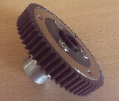
– 60 dts : suppression du moyeu,
– 60 dts : dés-épaississement à 10,
– 60 dts : alésage à 12 d’un coté, profondeur 4 (pour accueillir un roulement 6x12x4),
– 60 dts : alésage à 16 de l’autre coté,
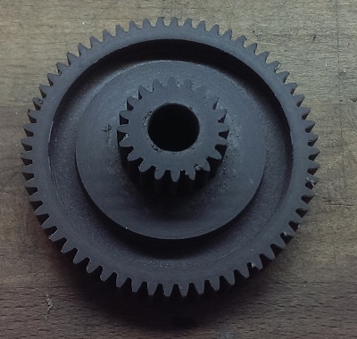
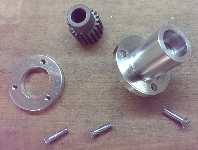
– 20 dents : dés-épaississement du moyeu à 5,
– 20 dents : tournage du moyeu, diamètre 16,
– 20 dents : alésage à 12 à l’opposé du moyeu, profondeur 4, pour accueillir un second roulement.
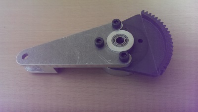
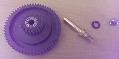
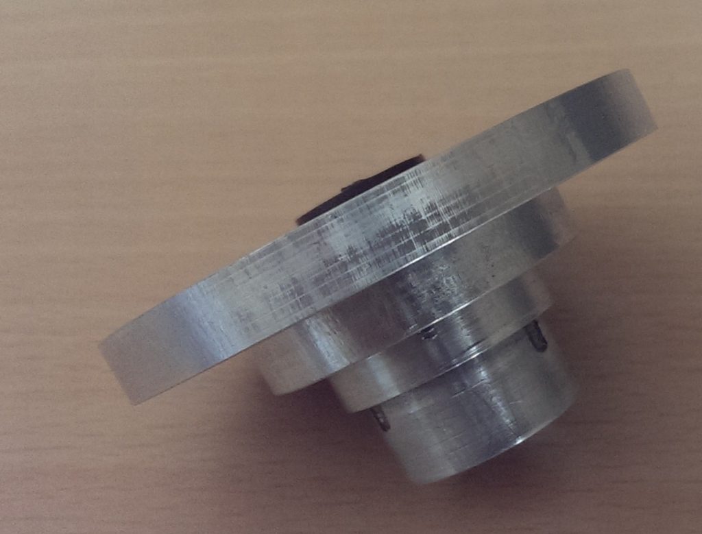
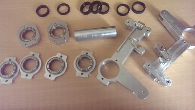
Il ne reste plus qu’à assembler les 2 pignons, et y introduire les 2 roulements …

Hello, I just found your posts. Fantastic Quadrant.
Would you be willing to share your drawings?
I would really like to build one like this for my simulator.
I don’t have your machinining skills but I would really like to try.
Kind Regards,
Randy
Thanks Randy,
you’re not the only one interested in the plans, I understand that.
But I was strongly recommended not to broadcast them (sidestick and throttle), because, in some respects, these devices are very close to the real ones.
On the other hand, I can, if you wish, answer specific questions and clarify certain specific points.
Michel
I think I can figure out most of it. I do appreciate your situation. It’s your design.
The one area I would like help with is the Trim axle assembly. Would you be willing to share that?
If not I will try to figure it out on my own.
Fantastic work.
Randy
Hello Randy,
no secrets about the trim axis! It seems to me that this subject is very detailed, tell me what you want me to develop more?
Michel
Yes you are correct. I was not paying attention. One thing though. If I may.
Are those bearing that the Throttles are then mounted on in the middle of the shaft?
Randy,
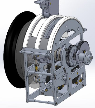
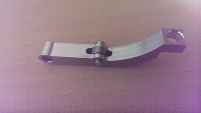
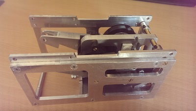
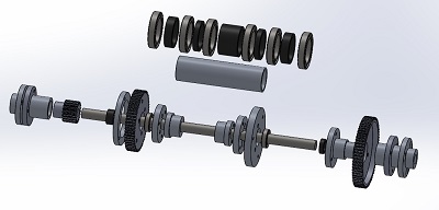
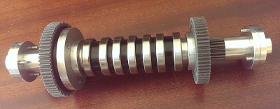
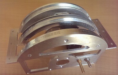
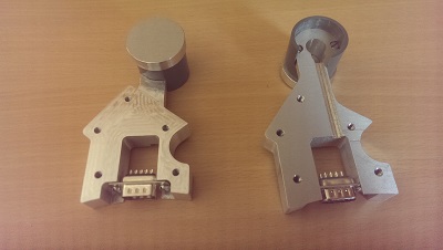
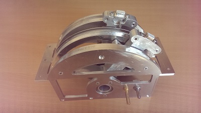
Each lever is mounted on 2 bearings, themselves mounted on the external axis (axis B on the scheme); this axis is itself mounted on 2 bearings, 1 on each side, on the frame; there are spacers between each of the 6 bearings; each bearing inserted into a bore and held by a cover.
have I answered your question?
Michel
Yes thank you. I appreciate your time. I will have to see if I can change the current model I am building. I have a OpenBuilds CNC but have not tried Doing Aluminum on it.
I am using mdf and acrylics as I do not have a local supplier for aluminum.
I also have a couple 3d Printers so I can probably print the gears and such in Nylon.
Lets see how it goes.
Randy
Well my throttle is coming along. I am doing something a little simpler for now just to get a handle on how the electronics will work before I get to fancy.
Could you tell me what type of potentiometers you used for the Trim Wheel and Throttle positions.
I could send a couple pictures of my progress if you like.
Thank you,
Randy
Hi Randy,
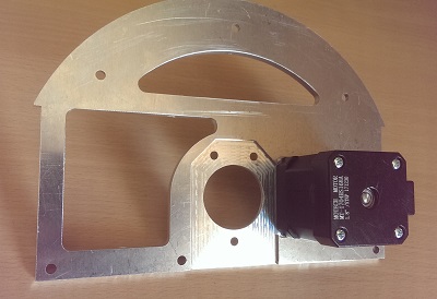
I used good quality cermet track potentiometer, 10 kohm ; you can see them in chapter “2 – La base”, pictures “Support” and “Assemblage intermédiaire”, the white square parts.
Yes, I would be happy to see the progress of your throttle !
Michel
Cermet Track Potentiometer? I am not sure what you mean by a Track Potentiometer.
Could you email me at rshuya@telus.net and I will send you those pictures.
Ok I understand the Term , track potentiometer now. I just had not heard that term before. I know it’s 10k but is it a single turn, 10 turn or constant turn type.
Considering it is on the trim wheel I would think you would need more than just a single turn.
Would a hall effect potentiometer or precision one be best for this?
Hi Randy,
the important point is the quality ! an other one is the size, because there is no much room for the potentiometer … there are single turn, it is just a matter of gears size, but they could be 10 turns.
However, for a single turn potentiometer, a large travel is better, and I don’t know if the hall effect potentiometers offer the 300 ° of a conventional potentiometer (the ones I built for the simulation are less than 180 °).
Michel
Ok thank you. I will get some good ones. I wish I could post a picture to show you what I am trying to accomplish. That would make it easier for me to describe my issues .
Hello again. I’m sure your getting tired of hearing from me but I am not giving up on this project. I have been able to create free movement in all the 3 axis. The throttles /Trim indicator and the Outside trim wheel can all move independent of each other.
But…. here is the problem or I should say here is where I am stuck.
No matter how I design the gearing The only options I see using your design is that you can either turn the Outside Trim Wheel as you have if I am correct but the Trim indicator Wheels remain stationary.
I have scoured the internet to find some indication of how the Trim Indicator Wheel is being driven and I have found only one source of a fellow rebuilding an OEM Quadrant. It looks as though the Trim indicator is controlled by a second Motor/pot and connected by a chain and sprocket.
Since I am guessing I ask you am I close to being correct. This is like the price is right game. No insult intended of course.
The only option I see from the way I have things is to install an additional panel in the middle of my design and splitting the outside axel, installing a sprocket ( belt drive) because of the distance and using a second motor and 10 turn pot on that.
Again I can’t post a picture to you so I hope you can visualize what I am saying.
I would also like to ask if I may post one of your images to the internet Simulator building community to see if someone there can assist me?
Thank you and have a great day,
Randy Shuya
Hi Randy,
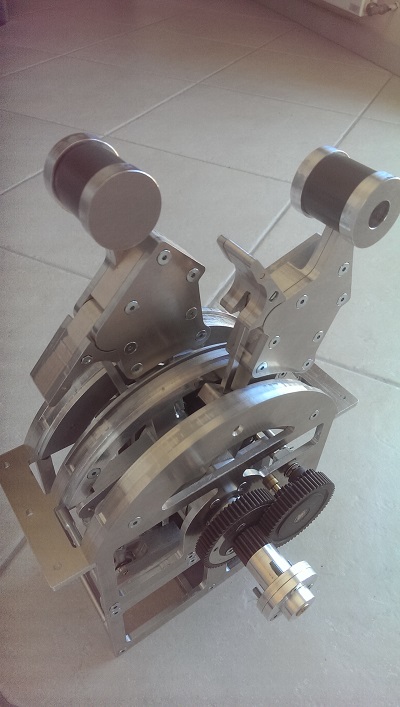
I am not sure I understand correctly ? the cone (trim indicator) does not turn when you turn the trim wheel?
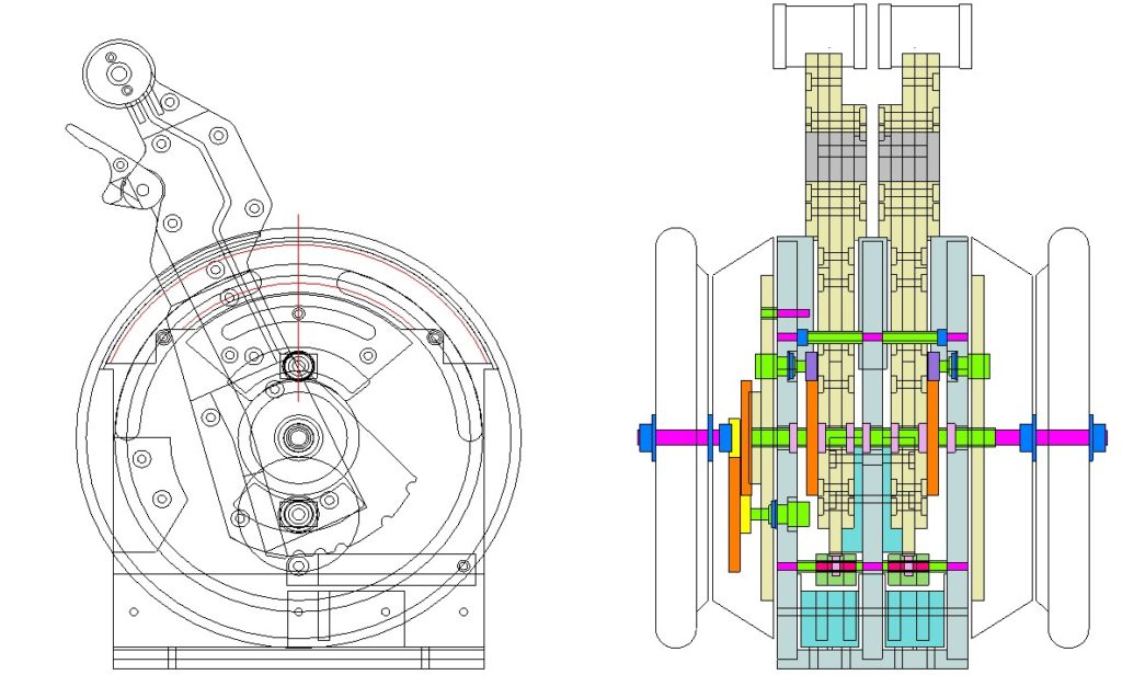
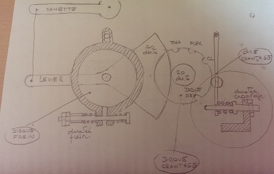
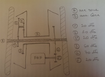
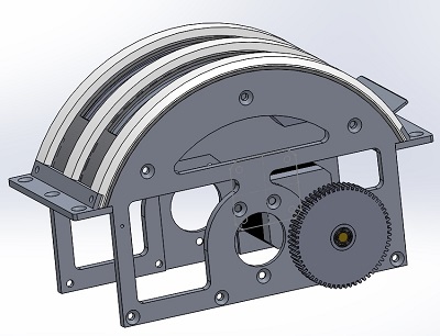
I can assure you that everything is working well ; you must carefully study the first drawing of chapter 3 : The trim :
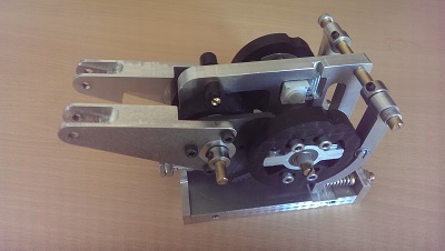
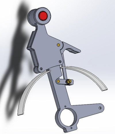
– When you turn the trim wheel, the axis “A” is driven, which turns the gear “1”, which turns the double gear “2 and 2 ‘”, which turns the gear “3”, which rotates the “B” axis, which rotates the cone.
the “A” axis also rotates gear “4”, which rotates gear “5”, which rotates the stepper motor (if it is not powered on, it can rotate ).
– In the other direction, if you make the stepper motor turn, it turns “5”, “4”, “A”, the wheel, and therefore the cone.
Michel
Ok back to the drawing board. There is just something I am not seeing I guess.
Must be my old age creeping up.
Dang.
If I could just build this one thing I would be happy.
Randy
Ok , perhaps my issue is the axle cone. The one I have been trying to use is not hollow so I am unable to visualize how to place the gears to drive it.
Would you please let me send you a couple of pictures of my work so that I can make the required adjustments. I’m begging you. Otherwise I might as well throw all this in the garbage.
I need your help and no one else can or will help me with this.
Kind regards,
Randy
Bonjour,
Beau travail, bravo !
Puis-je savoir de combien est le rapport entre le trim wheel et le cône, s’il vous plait ?
Merci +++
Bonjour Charles, et merçi,
Sur ce coup là, j’ai triché, car dans la réalité, ce rapport est je crois de l’ordre de 1 à 3,5 ; dans le cas présent, compte tenu du fait que le cône ne peut pas tourner 360° (il en est empéché par le train d’engrenages internes), le rapport est seulement de 1 à 9 ; dans la pratique, c’est vraiment un detail de faible importance : on ne se sert de la roue qu’une seul fois dans un vol, au sol … en vol, celà réduit simplement l’amplitude des rotations du trim.
Michel
Michel
bonjour, je viens de trouver votre site et je suis très impressionné par votre réalisation mais pourriez vous me détailler la conception des axes centraux, et leur intégration au sein de tout le système ah et aussi si vous avez gardé les plans des cônes rétroéclairés afin de pouvoir reproduire l’aspect extérieur de ceux ci. Aussi je ne comprends pas en quoi le cône ne pourrais pas tourner a 360° car les pignons ne passent qu’au centre des cônes. Dans la mesure ou vous ne pouvais pas diffuser vos plans, pourriez vous m’envoyer les photos de repère ainsi que (dans la mesure du possible ) me décrire plus en détail la conception de l’ensemble. Merci d’avance.
Paul
Bonjour Paul,
avez-vous bien lu ce sujet, je pense avoir vraiment décrit dans le détail la “conception des axes centraux” (voir chapitre 3) ! J’y ai en particulier mentionné un axe dit “secondaire”, décallé par rapport à l’axe principale, et qui empêche donc en effet une révolution des cones sur 360°.
Attention, ce projet n’est pas des plus simples, une lecture approfondie du sujet et sa traduction en plan détaillé s’impose, mais là, c’est à vous de jouer … pour moi, ce projet est déjà très loin.
Michel